Showing posts with label Networking Basics. Show all posts

Thursday, November 21, 2013

IP Address (Introduction to Subnetting)

Before we go to learn about subnetting.
First we need to know about IP Address. IP address is a numeric identifier assigned to each machine on
an IP network. It designates the specific location of a device on the network.
An IP address consists of 32 bits of information. These bits are divided into four sections, referred to as octets or bytes, each containing 1 byte (8bits). You can depict an IP address using one of three methods:
+) Dotted-decimal, as in 172.16.30.56
+) Binary, as in 10101100.00010000.00011110.00111000
+) Hexadecimal, as in AC.10.1E.38
All these examples truly represent the same IP address. Hexadecimal isn’t used as often as dotted-decimal or binary when IP addressing is discussed, but you still might find an IP address stored in hexadecimal in some programs. The Windows Registry is a good example of a program that stores a machine’s IP address in hex.
Network Addressing
The network address (which can also be called the network number) uniquely identifies each network. Every machine on the same network shares that network address as part of its IP address. In the IP address 172.16.30.56, for example, 172.16 is the network address.
The node address is assigned to, and uniquely identifies, each machine on a network. This part of the address must be unique because it identifies a particular machine—an individual—as opposed to a network, which is a group. This number can also be referred to as a host address.
In the sample IP address 172.16.30.56, the 30.56 is the node address.
IP address is divide by class. Below is the picture of IP Address Classes.
Network Address Range: Class A
The designers of the IP address scheme said that the first bit of the first byte in a Class A network address must always be off, or 0. This means a
Class A address must be between 0 and 127 in the first byte, inclusive.
Consider the following network address:
0xxxxxxx
If we turn the other 7 bits all off and then turn them all on, we’ll find the Class A range of network addresses:
00000000 = 0
01111111 = 127
So, a Class A network is defined in the first octet between 0 and 127, and it can’t be less or more. (Yes, I know 0 and 127 are not valid in a Class
A network. I’ll talk about reserved addresses in a minute.)
Network Address Range: Class B
In a Class B network, the RFCs state that the first bit of the first byte must always be turned on but the second bit must always be turned off. If you
turn the other 6 bits all off and then all on, you will find the range for a Class B network:
10000000 = 128
10111111 = 191
As you can see, a Class B network is defined when the first byte is configured from 128 to 191.
Network Address Range: Class C
For Class C networks, the RFCs define the first 2 bits of the first octet as always turned on, but the third bit can never be on. Following the same
process as the previous classes, convert from binary to decimal to find the range. Here’s the range for a Class C network:
11000000 = 192
11011111 = 223
So, if you see an IP address that starts at 192 and goes to 223, you’ll know it is a Class C IP address.
Network Address Ranges: Classes D and E
The addresses between 224 to 255 are reserved for Class D and E networks. Class D (224–239) is used for multicast addresses and Class E
(240–255) for scientific purposes, but I’m not going into these types of addresses in this book (and you don’t need to know them).
Network Addresses: Special Purpose
Some IP addresses are reserved for special purposes, so network administrators can’t ever assign these addresses to nodes. Table 3-4 lists the
members of this exclusive little club and the reasons why they’re included in it.
Class A Addresses
In a Class A network address, the first byte is assigned to the network address and the three remaining bytes are used for the node addresses.
The Class A format is as follows:
network.node.node.node
For example, in the IP address 49.22.102.70, the 49 is the network address and 22.102.70 is the node address. Every machine on this particular
network would have the distinctive network address of 49.
Class A Valid Host IDs
Here’s an example of how to figure out the valid host IDs in a Class A network address:
All host bits off is the network address: 10.0.0.0.
All host bits on is the broadcast address: 10.255.255.255.
The valid hosts are the numbers in between the network address and the broadcast address: 10.0.0.1 through 10.255.255.254. Notice that 0s
and 255s can be valid host IDs. All you need to remember when trying to find valid host addresses is that the host bits can’t all be turned off or all be
on at the same time.
Class B Addresses
In a Class B network address, the first 2 bytes are assigned to the network address and the remaining 2 bytes are used for node addresses. The format is as follows:
network.network.node.node
For example, in the IP address 172.16.30.56, the network address is 172.16 and the node address is 30.56.
Class B Valid Host IDs
Here’s an example of how to find the valid hosts in a Class B network:
All host bits turned off is the network address: 172.16.0.0.
All host bits turned on is the broadcast address: 172.16.255.255.
The valid hosts would be the numbers in between the network address and the broadcast address: 172.16.0.1 through 172.16.255.254.
Class C Addresses
The first 3 bytes of a Class C network address are dedicated to the network portion of the address, with only 1 measly byte remaining for the node
address. Here’s the format:
network.network.network.node
Using the example IP address 192.168.100.102, the network address is 192.168.100 and the node address is 102.
Class C Valid Host IDs
Here’s an example of how to find a valid host ID in a Class C network:
All host bits turned off is the network ID: 192.168.100.0.
All host bits turned on is the broadcast address: 192.168.100.255.
The valid hosts would be the numbers in between the network address and the broadcast address: 192.168.100.1 through 192.168.100.254.
Private IP Address
The people who created the IP addressing scheme also created what we call private IP addresses. These addresses can be used on a private network, but they’re not routable through the Internet. This is designed for the purpose of creating a measure of well-needed security, but it also conveniently saves valuable IP address space.
If every host on every network had to have real routable IP addresses, we would have run out of IP addresses to hand out years ago. But by using private IP addresses, ISPs, corporations, and home users only need a relatively tiny group of bona fide IP addresses to connect their networks to the Internet. This is economical because they can use private IP addresses on their inside networks and get along just fine.
To accomplish this task, the ISP and the corporation—the end user, no matter who they are—need to use something called Network Address Translation (NAT), which basically takes a private IP address and converts it for use on the Internet. (NAT is covered in Chapter 13, “Network Address Translation.”) Many people can use the same real IP address to transmit out onto the Internet. Doing things this way saves megatons ofaddress space—good for us all!
Source : CCNA Cisco Certified Network Associate S – Lammle_ Todd

Step By Step Cisco Router Configuration (Introduction II)

Ok. Before we start configure the router.
First of all, I want to explain about router.
What is router?
Router is a computer.
Router had a working process like a computer but a difference is Router only work from Layer 1 s/d Layer 3.
A computer work on Layer 7.
Well First I will describe about Router Component.
-CPU: Central Process Unit -> to do the process which mean the main core like brain in human body.
-ROM: Read Only Memory -> to save bootstrap program and scaled down IOS version, performing POST (same function with BIOS in PC)
-RAM: Random Access Memory -> for temporary memory
-NV-RAM -> to save configuration permanently
-Flash: -> to save IOS (same function with Harddisk in PC)
Now i will explain how the process in Router boot-up:
- Router will performing POST (Power On Self Test) to ensure that the hardware is on or not.
- After that load bootstrap program (Program that running the program which more bigger, load program into RAM)
- Locate and loading IOS
when locate, it will search in Flash. If in flash didn’t contain IOS, it will search in TFTP Server. If in TFTP Server didn’t have, it will scaled down IOS version.
- Locate and loading startup Configuration File.
when locate, it will search in NV-RAM. If in NV-RAM didn’t contain Configuration File, it will search in TFTP Server. If in TFTP server didn’t have, it will prompt Setup Mode.
Principe Routing Table
1.Every router had to make a self decision based on Routing table information
2.Routing table information in every router not necessarily same
3.Information about some way is n0t consist information about return path
You also must know about metric.
Metric is unit measurement for the software.
EIGRP using Bandwith for the metric. RIP using Hop for the metric.
Next we will start to know what is routing static and the example case for routing static.
Hope u enjoy it.

Step By Step Cisco Router Configuration (Introduction)

Before we start to configure router, there are a few things that you must know.
Cisco IOS software provides two levels of access to commands: user and privileged for security purpose.
The unprivileged user mode is called user EXEC mode. The privileged mode is called privileged EXEC mode and requires a password.
Below is table that describes some of the most commonly used modes, how to enter modes, and the resulting prompts.
The prompt helps you identify which mode you are in and , which command are available to you

How to use Help
In any command mode, you can get a list of available commands by entering a question mark (?).
To know a list of commands that begin with a particular character sequence, u can use question mark in the end
example
Router#co?
configure connect copy
To list keywords or arguments, enter a question mark in place of keyword or argument. Include a space before the question mark.
example
Router# configure ?
memory Configure from NVmemory
network Configure from a TFTP network host
terminal Configure from the terminal
You can also commands and keywords by entering just enough character to make the command unique from other commands.
For example
u can type show command with sh
en to enable
We will explain more in other subject. :D
Hope this blog can help u understand more.

Physical Layer

Now we would explain the last of OSI layer, the first/lowest of OSI layer.
Physical layer consists of the basic networking hardware transmission technologies of a network.
Physical layer is a fundamental layer underlying the logical data structures of the higher level functions in a network.
This layer is the most complex layer in the OSI architecture.
In this layer, it defines the means of transmitting raw bits rather than logical data packets over a physical link connecting network nodes. the bit stream may be grouped into code words or symbols and converted to physical signal that is transmitted over a hardware transmission medium.
for example, data transfer in modem (signal to digital).
The example device that work in this device is Hub, repeater, network interface card.
The main function of this layer :
1. Definition of Hardware Specifications: The details of operation of cables, connectors, wireless radio transceivers, network interface cards and other hardware devices are generally a function of the physical layer
2. Encoding and Signaling: The physical layer is responsible for various encoding and signaling functions that transform the data from bits that reside within a computer or other device into signals that can be sent over the network.
3. Data Transmission and Reception: After encoding the data appropriately, the physical layer actually transmits the data, and of course, receives it. Note that this applies equally to wired and wireless networks, even if there is no tangible cable in a wireless network!
4. Topology and Physical Network Design: The physical layer is also considered the domain of many hardware-related network design issues, such as LAN and WAN topology.

Data Link Layer

Right now, we are going to talk about Data Link Layer.
Data link layer had a function to make sure that message sent to correct device and translate message from network layer to bits form to transmitted by Physical layer.
In this layer, message is in form data frame with additional header which contain source address and destination hardware.
In device layer 3 (router), device worked to choose the best way to reach network destination, but the device didn’t care where the host is located. In Device layer 2 had responsibility to identified every device in network.
When host send package to another host, data link layer will frame the package with information data link control include hardware address, but if this package go through a router, this information will be left, router just receive the original package.
In Data link layer had 2 sublayers which is MAC and LLC.
*
Media Access Control (MAC) also know as 802.3.
this define how the package been replace by media. Physical address and logical topology being defined in here.
Logical topology is signal path which go trough a physical topology.
MAC may refer to the sublayer that determines who is allowed to access the media at any one time (usually CSMA/CD). Other times it refers to a frame structure with MAC addresses inside.
CSMA/CD (Carrier Sense Multiple Access with Collision Detection) is a access method that trace every possibility collision will happen. If a computer want to send data and detect that data which will be send is already in network, it will wait for a few times to try again send the data, so the collision can be avoid.
If in the checking step found another data transmission and being collision with the data which being send, the node must send again the request in a few minutes in random time.
There are generally two forms of media access control: distributed and centralized.
To make you more easy to understand,
for example in a conversation, If two people speak at the same time, they will back off and begin a long and elaborate game of saying “no, you first”.
The MAC determines where one frame of data ends and the next one starts – frame synchronization
There four means of frame synchronization.
- time based
- character counting
- byte stuffing
- bit stuffing.
*
The second of is:
Logical link control (LLC) also known as 802.2.
This sublayer had responsible to identify network layer protokol and then encapsulate it. Header LLC told to data link layer what should be done for package when frame is received.
For example:
a host that received frame and will saw header LLC to understand the packet destination in IP protocol on network layer. LLC is also give flow control and sequence the control bit.
A example device that work in Data link Layer is Switch and Bridges

Network Layer

Right now we discuss about Network Layer.
First of all, what is Network Layers? what is the main function of this layer?
The Network layer(usually called layer 3) manages devices addressing (logical addressing), tracks the location of devices on the network, and determines the best way to move data (routing data).
The devices that working in this layer of course is router. :)
Below is the flow for networking:
First, when a packet is received on router interface, the Destination IP address is checked. If the packet isn’t destined for that specific router, it will look up the destination network address in routing table.
Once the router chooses an exit interface, the packet will be sent to that interface to be framed and sent out on the local network. If the router can’t find an entry for the packet’s destination network in the routing table, the router drops the packet.
Two types of packets are used at the Network Layer: data and route updates.
Data packets
Used to transport user data through the internetwork. Protocol used to support data traffic are called routed protocols.
example: IP and IPX.
Route update packets
Used to update neighboring routers about the networks connected to all routers within the internetwork. Protocol that send route update packets are called routing protocols.
example: RIP,EIGRP,and OSPF.
The Routing table used in a router includes the following information:
Network address
A route must maintain a routing table for individual routing protocols because each routing protocol keeps track of a network with different addressing scheme.
Interface
The exit interface a packet will take when destined for a specific network
Metric
The distance to the remote network.Different routing protocols use different ways of computing this distance.
hop count
The number of routers a packet passes through en route to a remote network.
router break up broadcast domains and collision domains. (broadcast aren’t forwarded through a router).
To make u more understand more about broadcast domain and collision domain
below is the video of explanation broadcast and collision domains.

To make u more easier, i will review the point that you should remember in this section:
1. Routers, by default, will not forward any broadcast, multicast packets
2. Routers use the logical address in a Network layer header to determine the next hop router to forward the packet to
3. Routers can use access lists, created by an administrator, to control security on the types of packets that are allowed to enter or exit an interface
4. Routers can provide layer-2 bridging functions if needed and can simultaneously route through the same interface.
5. layer 3 devices provide connections between virtual LANs (VLANs).
6. Routers can provide quality of service (QoS) for specific types of network traffic.

Transport Layer

Before entering another layer in Lower layer, first of all we must know about transport layer.
What is transport layer? What is the function for this layer?
This layer segment and reassembles data into a data stream.
The example device /fitur for this layer is firewall.
There are 2 protocol in this layer that you must know.
The protocol is TCP and UDP.
TCP = transmission control protocol.
UDP = user datagram protocol
TCP is usually used by FTP. UDP is used by voice.
The Difference between TCP and UDP:
TCP
—-
connection oriented
Flow Control
3 way handshake
Overhead -> The sent data is more bigger than total size because it contain header information
Reliable
Header 20 byte
UDP

Connectionless
Header 8 byte
Fast data delivery
Unreliable
The Transport Layer is responsible for providing mechanisms for multiplexing upper-layer applications, establishing sessions, and tearing down virtual circuit.
It also hides detail of any network-dependent information from the higher layers by providing transparent data transfer.
Multiplexing is a technic that sending more than 1 information using 1 channel.
The purDatagrampose of multiplexing is to save the total of physical channel like cable, transceiver, optic cable,etc.
MTU (Maximum Transmission Unit) is a maximum data limitation that can being send by a one frame in Network Interface Layer in TCP/IP. Layer Network Interface is not desain to accept or sending frame that contain more than MTU that we config.a one Datagram IP is a must lower or same size with MTU or it can’t be encapsulation for sending.(Comer, 2001)

Application Layer, Presentation Layer & Session Layer

What is Application Layer?
In OSI communications model, the application layer provides server for an application program to ensure that effective communication with another application program in a network isi possible.
The application layer is not the application but it is a service layer that provide service:
1. To Make sure the other party is identified and can be reached.
2. To make sure either the message sender or receiver or both.
3. To make sure that necessary communication resources exist
(for example, is there any modem in the sender’s computer?)
4. To makes sure aggrement at both ends about error recovery procedures, data integrity and privacy
5. To specify protocol and data syntax rules at the application level
The example protocol that working in application layer :
HTTP,HTTPS,FTP,DHCP,TELNET,DNS,SNMP,SMTP,POP3,IMAP,etc.
Protocol is a rule or standart that set or permit that connection, communication and data move is happen between 2 or more device.
In other word, application layer is interface between application with network functionality.
Presentation Layer
Presentation Layer have a function to data translation for data which want to transmitted from application in format that can been transmitted in network.
Presentation layer has responsibility how data can be converted and formated for data transfer.
the example of conversion data is format text ASCII for document, .gif and JPG for image.
This layer create code convert , data translation, encryption and
The example protocol in this level is RTF,MIDI,JPEG,etc.
RTF (Rich Text Format) is a file format that lets you exchange text files between different word processors, even in different operating systems.
Session Layer
Session Layer is responsible for setting up, managing, and then seperate session between Presentation layer entities.
This layer also provides dialogue control between devices, or nodes.
It coordinate communication between systems, and serves to organize their communication by offering three different modes: simplex,half duplex and full duplex.
The protocol that work in this layer is NFS,SQL,RPC,X Windows, ASP, etc.

Basic Concept OSI Layer

Every people who wants to join in networking world must understand what is OSI layer.
we must overcome this concept, because OSI layer is the basic in networking.
What is OSI?
OSI(Open Systems Interconnection) is model product of OSI effort at the ISO. OSI is a resolution of standard and characteristic of a communications system in terms of abstraction layer.
which mean OSI is a model abstraction to help us know and differentiate the function network device and the system work.
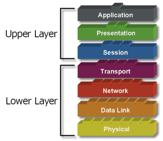
OSI layer is consist of 7 layer:
1. Application Layer
2. Presentation Layer
3. Session Layer
4. Transport Layer
5. Network Layer
6. Data Link Layer
7. Physical layer
Every layer has own specific responsibility for process data communication.
For example, one layer has responsibility to create connection between each other media, and the other layer has responsibility to correct if “error” happen during transfer data.
There are a few theory about this OSI layer. Some people difference this 7 layer in two groups (Upper Layer and Lower layer).
Upper layer is consist of Application Layer, Presentation Layer, Session layer.
Lower layer is consist of Transport layer, Network Layer, Data Link layer, Physical layer.
Upper layer is describe on application that user use and how the file being represented on computer.
For network engineer, the main part is lower layer.
lower layer is the main of data communication.
The main purpose of using model OSI is to help network desainer to understand function of each layer that have connection with communication data flow. Include type of network protocol and method of transmission
I will describe the function of each layer in other subject.
May this post can help u understand the OSI layer.

OSPF

OSPF. yup. i know you must be have a lot of question about OSPF.
OSPF as you know is a LSPR.
what you must know is the characteristic about OSPF:
- OSFP is a classless routing protocol.
- OSPF update with multicast(224.0.0.5 and 224.0.0.6)
- OSPF using Djistrak Algorithm to count metric.
- OSPF had AD 110
- OSPF had a fitur to Authentication
You also must known about 5 Type OSPF LSP:
- Hello -> to establish connection and maintain connection with another OSPF.
- DBD(Database Description) -> it contain database value in a router, and being used to database sinchronize with another router.
- LSR(Link State Request) -> To ask about information with an entry in DBD, if different with another router
- LSU(Link State Update) -> to answer LSR and to give a new information.
- LSACK(Link State Acknowledgement) -> To ack all LSP Packet.
- LSA(Link State Advertisemnt) -> Contain information about neighbor network (Cost).
To understand more, let us practice using packet tracer.
Below is the topology

I will skip giving IP Intefaces because i assume you already know how to set IP.
now let set ospf configuration in Router.
Below is the configuration for its
HQ:
network 192.168.158.0 0.0.0.127 area 0
network 192.168.158.128 0.0.0.63 area 0
network 192.168.159.96 0.0.0.3 area 0
network 192.168.159.100 0.0.0.3 area 0
R1:
network 192.168.159.64 0.0.0.31 area 0
network 192.168.158.192 0.0.0.63 area 0
network 192.168.159.96 0.0.0.3 area 0
R2:
network 192.168.157.0 0.0.0.255 area 0
network 192.168.159.0 0.0.0.63 area 0
network 192.168.159.100 0.0.0.3 area 0
Hope this tutorial can help you more understand the concept ospf.
Next time we will learn more about combining ospf,eigrp and rip in a network.

EIGRP (Enhanced Interior Gateway Routing Protocol)

Okay.. we already learn about Distance vector routing protocol (RIPv1&2).
and now we will start with EIGRP.
EIGRP is an Enhanced from IGRP and this protocol was cisco proprietary.
Ok let’s start to learn EIGRP. But wait.. why we start from EIGRP, not the IGRP.
Nowadays people already leave IGRP. They are already migrate to EIGRP. That why we skip to learn about IGRP.
But don’t worry, I will tell a little about IGRP before we learn more about EIGRP.
So let say, what is the difference between IGRP and EIGRP?
good question, First IGRP and EIGRP use different Algorithm.
IGRP using Bellman-Ford, otherwise EIGRP using DUAL algorithm.
Second, IGRP are clasfull routing protocol, EIGRP are classless routing protocol.
IGRP using Periodic Update every 90 second, otherwise EIGRP using Bounded Update.
Sometimes EIGRP is also being called “Hybrid Routing Protocol) because this protocol have a surplus in Distance Vector Routing Protocol (DVRP) and Link State Routing Protocol (LSRP), although EIGRP is being catagorized to DVRP.
Characteristic of EIGRP:
=> Using RTP (Reliable Transport Protocol) in Layer 4
=> EIGRP using 3 Update type to update the Routing table information (Bounded, Triggered, Partial).
=> EIGRP using DUAL (Diffusing Update Algorithm) to count metric. The main function of DUAL is to prevent routing loop.
=> EIGRP had 3 table :Routing table, Topology table, and Neighbor Table.
=> EIGRP had authentication Feature.
=> Automatic Summarization
=> sending with multicast (224.0.0.10)
=> AD EIGRP (Internal EIGRP =90, External EIGRP =170, Summary EIGRP =5)
The Advantages EIGRP than the other routing protocol.
- Fitur PDM (Protocol Dependant Module) which support multiple network protocol (IP,IPX,Appletalk)
- It is also support unequal load balancing
- save backup path
- Combining the Advantages from DVRP (easy to config and not using much processor) and LSRP ( fast convergence & support Complex topology)
EIGRP had 3 table
- Routing Table
- Neighbor table : Information directly connected network that join EIGRP.
- Topology table : Information for all router that join EIGRP
5 EIGRP Packet Type:
1. Hello Packet => to establish connection with directly connected network and maintain those connection.
2. Update Packet => to sending update to another router that join EIGRP
3. Query Packet => to ask another router about the location network if there are some network down.
4. Reply Packet => to answer query packet
5. Acknowledge Packet => to ack all EIGRP packet except Hello packet.
To understand more about EIGRP, let us start below exercise.
Below is the network topology:
I will not explain how to set the IP address and etc. I assume you already understand. If you don’t understand how to set IP, you can see back in my previous post.
After set all IP address, first we go to Router 0.
##: noted
Router>en
Router#conf t
Router(config)#router eigrp 10
##10 is a number for the Autonomous System (AS)
Router(config-router)#network 192.168.1.0
Router(config-router)#network 192.168.0.0
##Add directly Connected Network
Router(config-router)#exit
Router(config)#exit
Go to Router 1
Router>en
Router#conf t
Router(config)#router eigrp 10
Router(config-router)#network 172.10.0.0
Router(config-router)#network 192.168.0.0
Router(config-router)#exit
Router(config)#exit
After that u can try to PING each other PC in those network to make sure the network is already connected each other.

RIP(part II)

Last time, we already learn about RIPv1. in this section, we will learn about RIPv2.
Characteristic of RIPv2:
- RIPv2 is a Distance Vector Routing Protocol.
- RIPv2 is a classless routing protocol (Support VLSM, CIDR and Supernet)
CIDR -> Class Inter Domain Routing
CIDR is a technic to combine a few route become one route, to save routing table and traffic for routing update
- RIPv2 is also using UDP with port 520
- RIPv2 using hop count for the metric
- Max Hop in RIPv2 is 15. 16 is unreachable
- Administrative Distance in RIPv2 is 120
- RIPv2 need 30second to update by multicast (224.0.0.9)
- By default, RIPv2 do automatic summarization to become classless
- RIPv2 had Feature Authentication to enable password for using RIP
In RIPv2 had a loopback interface.
Loopback interface is an interface that working virtual, to simulate a network. (didn’t need to no shut, because by default is already up).
by command
Router(config)#interface loopback
Router(config-if)#ip address
By default, cisco router didn’t enable RIPv2. to enable, u must use command version 2.
Router(config)#router rip
Router(config-router)#version 2
In RIPv2, is also had a Null Interface.
Null Interface is an Exit Interface by virtual, usually being used to distribute static route summary in routing protocol.
This interface will not do data forward, so the package that come in this interface will be drop.
command:
ip route 192.168.0.0 255.255.0.0 null 0
Redistribute static is usually use for distribute to static route to directly connected routes.
to use redistribute static route, we can use command:
Router(config-route)#redistribute static
Ok. Now we are going to do practice RIPv2
In this section, i will not describe a full detail information for this topology network.
But i will give the configuration below.
First we go to router1
Router>en
Router#conf t
Router(config)#interface fastEthernet 0/1
Router(config-if)#ip address 192.168.1.1 255.255.255.0
Router(config-if)#no shutdown
Router(config-if)#ex
Router(config)#interface fastEthernet 0/0
Router(config-if)#ip address 10.0.0.1 255.0.0.0
Router(config-if)#no shutdown
Router(config-if)#ex
Router(config)#router rip
Router(config-router)#version 2
Router(config-router)#network 192.168.1.0
Router(config-router)#network 10.0.0.0
Router(config-router)#ex
Router(config)#ex
After finished configured router 1, now we go to router 2
Router>en
Router#conf t
Router(config)#interface fastEthernet 0/1
Router(config-if)#ip address 172.16.0.1 255.255.0.0
Router(config-if)#no shutdown
Router(config-if)#ex
Router(config)#interface fastEthernet 0/0
Router(config-if)#ip address 10.0.0.2 255.0.0.0
Router(config-if)#no shutdown
Router(config-if)#ex
Router(config)#router rip
Router(config-router)#version 2
Router(config-router)#network 10.0.0.0
Router(config-router)#network 172.16.0.0
Router(config-router)#ex
Router(config)#ex
To check your configuration is already correct or not. you can try to ping.

RIP (part I)

Right now we will discuss about RIP(Routing Information Protocol).
There are two type of RIP that being used.
That is RIPv1 and RIPv2.
In this part, we will discuss about RIPv1 and example exercise about how to using RIPv1.
RIPv1
Below is the Characteristic RIPv1:
- RIPv1 is a distance vector routing protocol
- RIPv1 use hop count as metric
- RIPv1 is a classful routing protocol
- max hop count in RIPv1 is 15. if 16, it means unreachable.
- RIPv1 send periodic update every 30 second with broadcast
- RIPv1 using protocol UDP with port 520
- RIPv1 by default running auto-summary
- RIPv1 can send packet update RIPv1 and receive packet update RIPv1 & RIPv2
- In Cisco, RIPv1 have AD (Administrative Distance) 120.
When installation, router-router that running RIP will broadcast packet request to another router to ask network that another router have.
Another Router will receive request packet and sending response.
After that they will sharing each network information.
to enable RIP, we can use command:
config#router rip
to add directly connected network that will being broadcast, we can use command:
config-router# network {classful-network-address |network address}
this command can be input after we enable RIP first.
In RIPv1, there are passive interface.
Passive interace is an interface that being participate but didn’t send any update.
to create passive-interface, we can use command
config-router#passive interface
this command can be input after we enable RIP first.
Right now we will learning update algorithm for RIPv1
1.Sending Update
RIPv1 will compare major network info with major network sending interface.
if same:
RIPv1 will check SubnetMask(SM) info with sending interface SubnetMask.
if check SM infor with sending interface SM same, RIPv1 will send the info, otherwise it will not send
otherwise:
RIP will summarize info into it’s major
2.Receiveng update
RIP will compare between network info with major network receiving interface
if same RIP will install with SM interface.
Otherwise RIP will check if major network info is same with each directly connected major network
if there is a same major network, RIPv1 will not install(discontigous), otherwise it will install with SM default class
Major network is same with classfull SM
Automatic summarization.
In RIP, it also have characteristic Automatic summarization
The Advantages for Automatic summarization is automatic and simple.
The Disadvantages:
- If network using VLSM, the RIP can’t be convergence
- If discontigous, network can’t be convergence
- load balancing could be wrong
Below we will practice for case RIPv1
please click to enlarge the picture
Picture Information
Router1(Router_ATD)
fa 0/0 : 172.16.0.1 /24
serial 2/0 : 172.16.1.1 /30
Router2(Router_ISB)
fa0/0 : 192.168.3.1 /24
Serial 2/0 : 172.16.1.2 /30
serial 3/0 : 10.0.0.1 /30
Router3(Router_LHR)
fa 0/0 : 192.168.4.1 /24
serial 2/0 : 10.0.0.2 /30
now lets begin the configuration
first we go to Router1
Router> en
Router#configure terminal
Router(config)#hostname Router_ATD
Router_ATD(config)#interface fastEthernet 0/0
Router_ATD(config-if)#ip address 172.16.0.1 255.255.255.0
Router_ATD(config-if)#no shutdown
Router_ATD(config-if)#exit
Router_ATD(config)#
Router_ATD(config)#interface se2/0
Router_ATD(config-if)#ip address 172.16.1.1 255.255.255.252
Router_ATD(config-if)#no shutdown
Router_ATD(config-if)#exit
Router_ATD(config)#router rip
Router_ATD(config-router)#network 172.16.0.0
Router_ATD(config-router)#network 172.16.1.0
Router_ATD(config-router)#no auto-summary
Router_ATD(config-router)#passive interface fa0/0
Router_ATD(config-router)#exit
we use command no auto-summary because in this topology didn’t need auto summary.
for command passive interface fa 0/0, this command is to make fa0/0 didn’t send update routing table from fa 0/0 and still get update routing table from another router.
command
Router_ATD(config-router)#network 172.16.0.0
Router_ATD(config-router)#network 172.16.1.0
is to add network from directly connected network.
now we go to router 2
Router> en
Router#configure terminal
Router(config)#hostname Router_ISB
Router_ISB(config)#interface fastEthernet 0/0
Router_ISB(config-if)#ip address 172.168.3.1 255.255.255.0
Router_ISB(config-if)#no shutdown
Router_ISB(config-if)#exit
Router_ISB(config)#
Router_ISB(config)#interface se2/0
Router_ISB(config-if)#ip address 172.16.1.2 255.255.255.252
Router_ISB(config-if)#no shutdown
Router_ISB(config-if)#exit
Router_ISB(config)#interface se2/0
Router_ISB(config-if)#ip address 10.0.0.1 255.255.255.252
Router_ISB(config-if)#no shutdown
Router_ISB(config-if)#exit
Router_ISB(config)#router rip
Router_ISB(config-router)#network 192.168.3.0
Router_ISB(config-router)#network 172.16.1.0
Router_ISB(config-router)#network 10.0.0.0
Router_ISB(config-router)#no auto-summary
Router_ISB(config-router)#passive interface fa0/0
Router_ISB(config-router)#exit
let us begin with Router 3
Router> en
Router#configure terminal
Router(config)#hostname Router_LHR
Router_LHR(config)#interface fastEthernet 0/0
Router_LHR(config-if)#ip address 192.168.4.1 255.255.255.0
Router_LHR(config-if)#no shutdown
Router_LHR(config-if)#exit
Router_LHR(config)#
Router_LHR(config)#interface se2/0
Router_LHR(config-if)#ip address 10.0.0.2 255.255.255.252
Router_LHR(config-if)#no shutdown
Router_LHR(config-if)#exit
Router_LHR(config)#router rip
Router_LHR(config-router)#network 10.0.0.0
Router_LHR(config-router)#network 192.168.4.0
Router_LHR(config-router)#no auto-summary
Router_LHR(config-router)#passive interface fa0/0
Router_LHR(config-router)#exit
To prove it, u can try ping from one router to other router.
Hope this can help u to understand more about RIPv1.

Distance Vector Routing Protocol

As we learn in previous subject, Distance Vector Routing protocol(DVRP) is Routing protocol that know about direction and distance to network destination.
The example of DVRP is RIP, IGRP, and EIGRP.
First we will discuss about RIP.
RIP (Routing Information Protocol)
In RIP, Routing update send by broadcast (RIPv1) and Multicast (RIPv2) every 30 second.
Information that sent by RIP is routing table.
IGRP (Interior Gateway Routing Protocol)
IGRP is protocol that only can run in cisco device (Cisco Proprietary). IGRP send periodic update every 90 second.
EIGRP (Enhanced Interior Gateway Routing Protocol)
EIGRP is the enhanced version for IGRP. It also cisco proprietary.
EIGRP had a feature unequal cost load balancing. It is also being called “hybrid” routing protocol because it had the benefit of DVRP and LSRP (fast convergence, low CPU processing, scalable, etc).
This protocol using DUAL (Diffusing Update ALgorithm) algorithm to count shortest path/metric.
In EIGRP there is no periodic update, routing update is being send if there are any changes in topology.
In DVRP, algorithm that being used is “Bellman-Ford Algorithm”
In RIP, There are 3 type of timer:
1. Invalid Timer (180s)
if information about the path is not being received in 180 second, the path will be marked invalid/unusable.
2. Flush Timer (240s)
If information about the path is not being received in 240 second, the path will be deleted in routing table.
3. Hold down Timer (180s)
One of the method to prevent routing loop.
Routing loop is a condition where a package still round without ever reach destination network.
EIGRP didn’t send periodic update but it send update when:
- Triggered update : send update if there are any changes in topology
- Bounded update : send update only to router that needed.
- Partial update : just send information routing that being needed.
RIP also had fitur triggered Update.
To prevent collision in sending periodic update in multi-access topology(hub-only), Random Jitter (RIP_JITTER) in RIP do randomize periodic update time between 25 until 30 second.
There are a few mechanism to prevent routing loop in DVDRP:
- Prevent Count to Infinity
Wrong Route wil being marked infinity / metric = 16
- Hold Down Timer
The dead route will being marked “down” and can only back if the interface is on or there are route to those network with a small metric.
- Split Horizon
Router will not send information about route to interface that it will received those information.
- TTL

Routing Protocol & Dynamic Routing (part II)

Okay.. let continue to round 2 :D
First we will learn about AD or Administrative Distance.
Administrative distance (AD) is a router’s feature to choose best way when there are two or more than way to reach same destination with two different routing protocol. Administrative distance shows reliability from a routing protocol.
Every routing protocol being priority from another with value Administrative Distance (AD) Help.
The more smaller AD, the more high the value. If there are two or more routing protocol that run and send to same network, routing protocol will being choose with the smallest AD.
For your reference, u can see below default value table of AD in Cisco Router:
Please click in a picture to enlarge the picture.
In Routing protocol, u also must know about Load Balancing.
Have u ever heard about Load Balancing?
What is Load balancing?
Load Balancing is distribution of traffic to two interface or more with same network destination.
Load Balancing is divide with 2 type: Equal Cost Load Balancing and Unequal Cost Load Balancing.
Equal Cost Load Balancing
if there are more than 1 way send to same network destination with same metric, the traffic load will being divide equal.
Unequal Cost Load Balancing
if the metric is different, it must being done with routing protocol (IGRP & EIGRP).
To show in a network using load balancing or not, we can use command “show ip route”.
Let’s take a break a little. :)
after this, we will continue explain more about Distant Vector Routing Protocol.

Routing Protocol & Dynamic Routing (part I)

Today our subject is Routing Protocol and Dynamic Routing
First let us discuss about Routing Protocol.
Routing Protocol is protocol which had function to change routing information between each router automatic by sending update to neighbor router.
There are 2 type of Routing protocol that you need to know, that is Classful and Classless.
Classful routing protocols do not send subnet mask information with their routing updates. A router running a classful routing protocol will react in one of two ways when receiving a route:
• If the router has a directly connected interface belonging to the same major network, it will apply the same subnet mask as that interface.
• If the router does not have any interfaces belonging to the same major network, it will apply the classful subnet mask to the route.
Belonging to same “major network” simply indicates that they belong to the
same “classful” network. For example:
• 10.3.1.0 and 10.5.5.0 belong to the same major network (10.0.0.0)
• 10.1.4.5 and 11.1.4.4 do not belong to the same major network
• 192.168.1.1 and 192.168.1.254 belong to the same major network (192.168.1.0)
• 192.168.1.5 and 192.167.2.5 do not belong to the same major network.
Take the following example (assume the routing protocol is classful):

If Router B sends a routing update to Router A, it will not include the subnetmask for the 10.2.0.0 network. Thus, Router A must make a decision.
If Router A has a directly connected interface that belongs to the same major network (10.0.0.0), it will use the subnet mask of that interface for the route.
For example, if Router A has an interface on the 10.4.0.0/16 network, it will apply a subnet mask of /16 to the 10.2.0.0 network.
If Router A does not have a directly connected interfacing belonging to the same major network, it will apply the classful subnet mask of /8. This can obviously cause routing difficulties.
When using classful routing protocols, the subnet mask must remain consistent throughout your entire network.
example of Classful routing protocols is RIPv1 and IGRP.
Now let us go to Classless Routing protocol.
Classless routing protocols do send the subnet mask with their updates. Thus, Variable Length Subnet Masks (VLSMs) are allowed when using classless routing protocols.
example of Classless routing Protocol is RIPv2, EIGRP, OSPF and IS-IS.
There are a few term that you need to know.
Below is the term:
Interior Gateway Protocols (IGP)-> Routing protocol that working to connect router inside same “Autonomous System”
Exterior Gateway Protocols (EGP)-> Routing Protocol that connect between each “Autonomous System”
Border Gateway Protocol (BGP)-> Routing protocol that developed from EGP which connect between “Autonomous System”
Autonomous System -> is a set of router/network device which locate inside same scope administrative
Distance Vector Routing Protocol -> Routing protocol that know about direction and distance to network destination
Distance-vector routing protocols use the Bellman-Ford algorithm, Ford–Fulkerson algorithm, or DUAL FSM (in the case of Cisco Systems’s protocols) to calculate paths.
Distance Vector is implemented in a simple network. Distance Vector had character slow convergence and send periodic update in router’s routing table which directly connected
Link state Routing Protocol -> Routing Protocol that know all topology in a network
Link state is implemented in a large network and need more knowledge. Link state had character Fast convergence.
Link state track status and type connection each link and generate counted metric based on another factor.
Link state protocol know what is the uplink or downlink, how many cost and time to reach destination/
Link state protocol will take a way that have a lot of hop and fast than a slow way that have a little hop.
Now let us go to Dynamic Routing.
Before we describe more about Dynamic Routing. I want to flashback a little about Static Routing.
For further information, u can see in my last blog with subject Route protocol.
Benefit using static Routing
- More secure
- less CPU resource
- More easy to known and configured
Weakness using Static Routing
- susceptible with any misconfiguration
- any changes in topology will make all router need to be configured
- not scalable
Benefit using Dynamic routing
- more scalable
- any change in topology just need to configure in new router or changed router.
- infrequently happen misconfiguration
Weakness using Dynamic Routing
- less secure
- More CPU resources
- need more knowledge
Metric -> unit of measure for the distance of a route ( the smaller is better)
RIP using Hop Count (Max 15)
IS-IS & OSPF using cost (Open Standart)
IGRP & EIGRP using bandwith, delay (by default), Reliability, load (Cisco Proprietary)